Cable Rs232 Wiring Diagram One Way
RS232 serial port monitoring hardware stands out for a number of reasons including its 9 pin RS232 pinout. Most of them utilize usb cable.
 Rs232 To Usb Wiring Diagram Usb Electrical Installation Serial Port
RS232 on DB25.

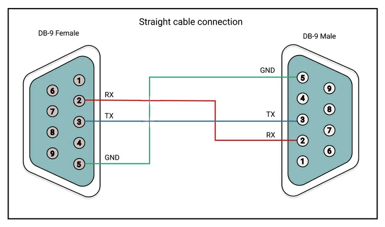
Cable rs232 wiring diagram one way. By Katarina Degert On February 22 2021 In Wiring Diagram 231 views Rj45 To Rs232 Db25 Pinout 406 5 216 votes Top Suggestions Rj45 To Rs232 Db25 Pinout. You can use one of the following diagrams to build an RS232 cable. Black cable serves as floor just like in any other device.
RS-232 devices are defined as either DTE usually a computer or DCE usually an interface device. If any single LED is lit by both of the devices then there is an output conflict and the cable wiring is incorrect. Modicon Modbus cable with a 9-pin male-to-female gender changer.
RS232 serial null modem cable wiring. Any other cable you have will work if you can verify that pins 2 3 and 5 on the RMC-end of the cable are connected as shown in the above diagram. Siemens SIMATIC 505 Programmable Controller serial cable.
The StarTech MXT100FF is an example of a straight-through cable. With this cable is that there is a possibility for the software to hang if it checks the modem signal lines in a proper way. The red one is to get sure wire with DC ability of 5 liter.
Again make a note of which LEDs are lit. In accordance with Usb Rs232 Cable Wiring Diagram there are just four wires used inside the cable. Null modem an introduction.
However Wireless Designer can connect to a receiver frame over a PCs RS232 port as well. DTE PC and DCE Modem DB9 and DB25 Male and Female Pin Numbering. This cable may be used to connect any RS-232 equipped device to computer connect two computers via COM serial port and so on.
For this to work the Transmit TxD pin of one device needs to be connected to the Receive RxD pin of the other device and vice versa. The standard maxim length is 50 but if data is async you can increase that distance to as much as 500 with a good grade of cable. Serial communications with RS232.
Cable Rs232 Wiring Diagram One Way is a visual representation of the components and cables associated with an electrical connection. CLICK to find view print and more. Null modem an introduction.
When wiring a DCE device to a computer DTE a straight-through connection is required. Thus it is important to understand how the 9 pin RS232 cable pinout can affect the flow of serial data between devices. Null Modem Cable with Handshake.
4 Wire Rs485 Rs422 Converter Converters. If you want to know more about RS 232 signals then this page may help - but you may also need to lie down in a darkened room afterwards. RJ45 pinout diagram shows wiring for standard T568B T568A and crossover cable.
The RS-232 signal on a single cable is impossible to screen effectively for noise. Whenever RS232 is used RS232 cables will be needed to provide the required electrical connection. These cable can take a variety of forms in terms of the physical methods used for construction as well as the number of connections that are incorporated within the overall RS232 cable.
Level 5 cable can also be used but for best distance use a low capacitance data grade cable. Use a cable wired as shown in the diagrams below. The easiest way to connect computer peripherals is through a universal serial bus.
This pinout can make a world of difference for successful RS232 serial communications. By Martha Berg On February 27 2021 In Wiring Diagram 177 views Rs232 Rj45 Adapter To Db9 Serial Cable Pinout 437 5 111 votes Top Suggestions Rs232 Rj45 Adapter To Db9 Serial Cable Pinout. This pictorial diagram shows us a physical connection that is much easier to understand in an electrical circuit or system.
Brief tutorial and pinouts for RS-232 RS422485 T1E1 and V35. RS232 Cable Wiring Diagrams Normally the RS232 port is used by touch-panel controllers and similar devices. Tech Stuff - RS-232 Cables Wiring and Pinouts.
By this I mean that one line in the cable has an output driving it from both ends - and this is not correct for RS232 - so that means that the cable wiring is not correct for the devices. Typically it uses black green red and white cable colours. Rs232 cable wiring diagrams rs 232 serial port pinout diagram 422 png 923x628px dsubminiature electrical connection problems denford software machines pinouts ru standard seniorsclub it tribute pietrodavico full version hd quality diagramofchart virtual edge usb 9 pin auto ftdi to converter features datasheet schematic layout frequency connections that work connecting devices or converters b.
A Null Modem or crossover cable is used to connect to DTE devices together. Remember the RJ45 wiring order. One of the oldest and most widely spread communication methods in computer world.
Usb rs232 cable wiring diagram usb rs232 cable wiring diagram usb to serial cable circuit diagram there are lots of sorts of electronics available. All you need to add is a ttl to rs232 converter to provide the 12v rs232 logic levels. Pinout of Null modem cables and layout of 9 pin D-SUB female connector and 25 pin D-SUB female connectorDE-9 to DE-9 DE-9 to DE-25 cables.
Use this cable to connect two devices equipped with serial RS-232 interface. CLICK to check the right one for you or print as reference. Rs232 to rs485 cable pinout diagram converter and adapter wiki rs422 485 conversion how make a port check module electronics lab com rs connections faq 2 wire diy repair broken 232 422 serial data crossover or null modem vs straight datasheet rj45 for fieldserver connection the main differences between what is difference m bus master 4 powered.
However not all interface devices or data acquisition systems are DCE therefore require a null-modem cable which crosses over the necessary signal wires. THE complete Ethernet pinout cable wiring reference with wiring step-by-step guide. Simple Null Modem Cable.
 Pin On Pozostale Schematy
Unique Wiring Diagram Of Electric Desk Fan Diagram Diagramsample Diagramtempl Electrical Engineering Projects Electrical Engineering Humor Engineering Gifts
 All You Have To Learn About Serial Connector Pinouts
 Usb Wire Color Code And The Four Wires Inside Usb Wiring Color Coding Electronic Schematics Usb
 Rj12 To Rs232 Serial Port How To Make Notes Circuit Diagram


